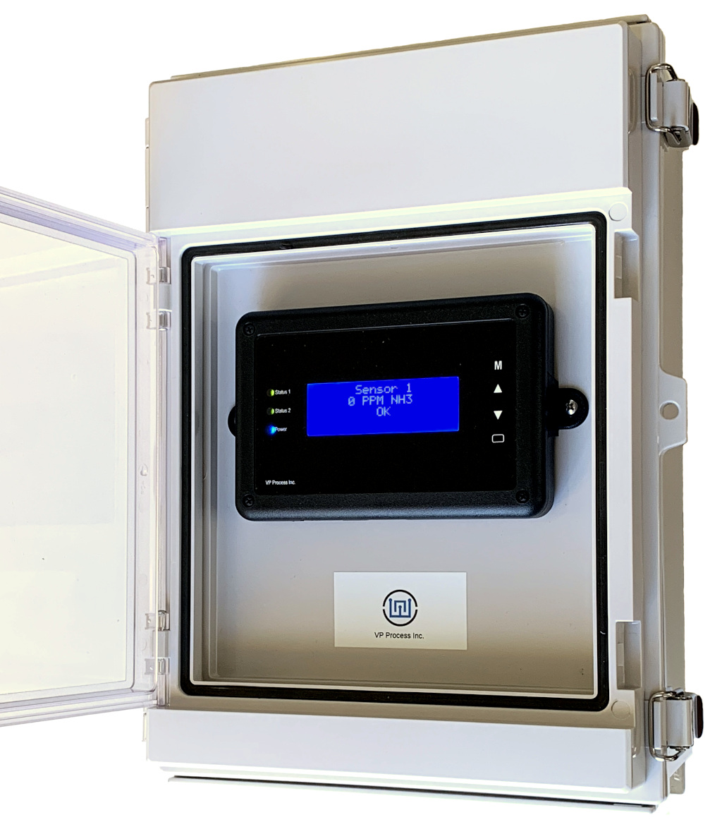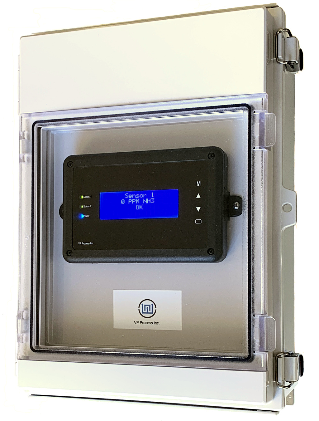
Enclosure IP66 with Dual Door Access
The VP-KB1 is used in gas detection applications that require monitoring of analog transmitters. Standard features like 4x20 character LCD’s, LED alarm indicators,pushbutton interface, relay outputs, universal power supply with 24 VDC field power, and a comprehensive programmable sensor input types gives the VP-KB1 ultimate flexibility.
Standard Features
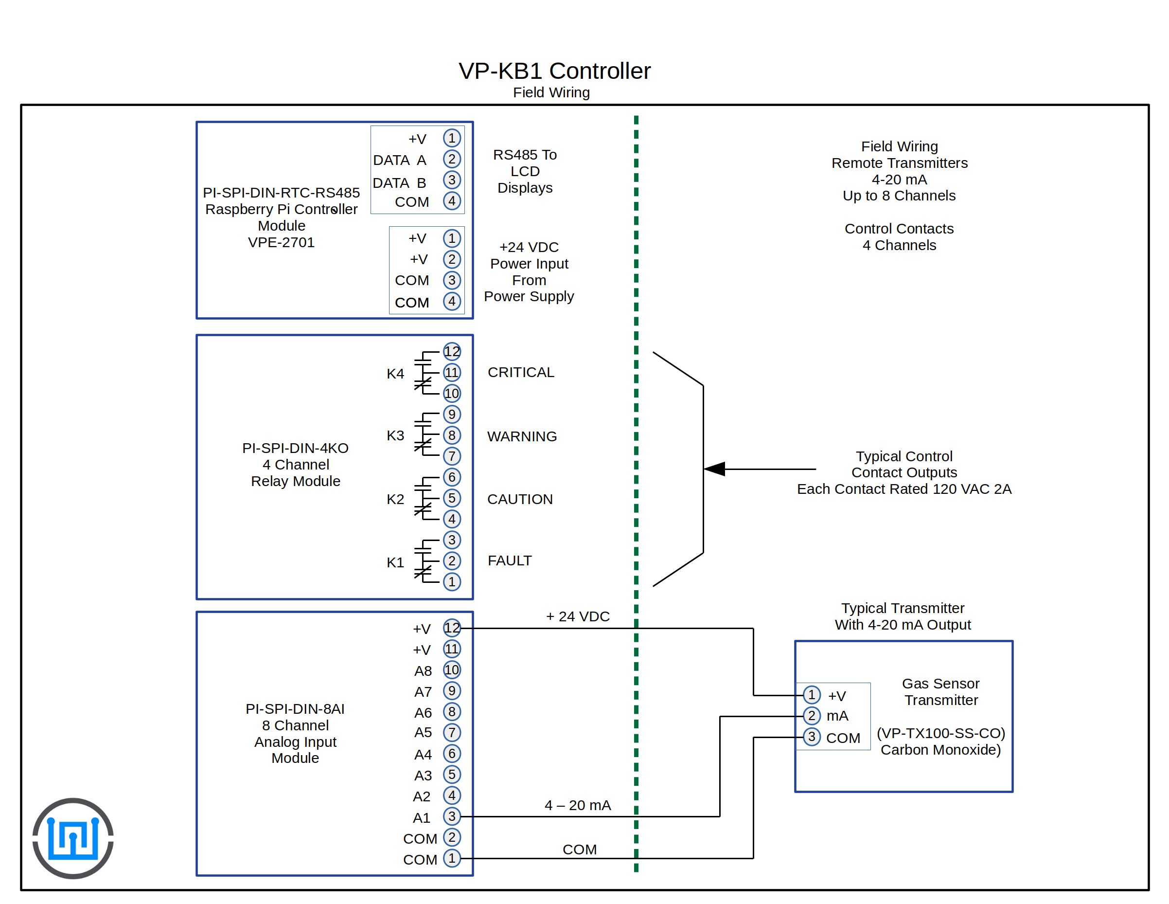
- Up to 8 Remote Transmitters (4-20 mA)
- Sensor Type Programmable - See Chart Below
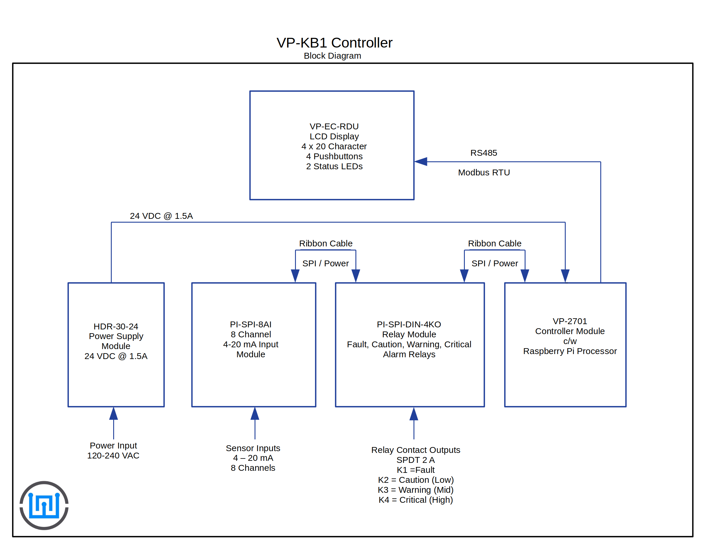
- 4 Control Relays (SPDT 2A) Fault, Low, Mid and High Alarm
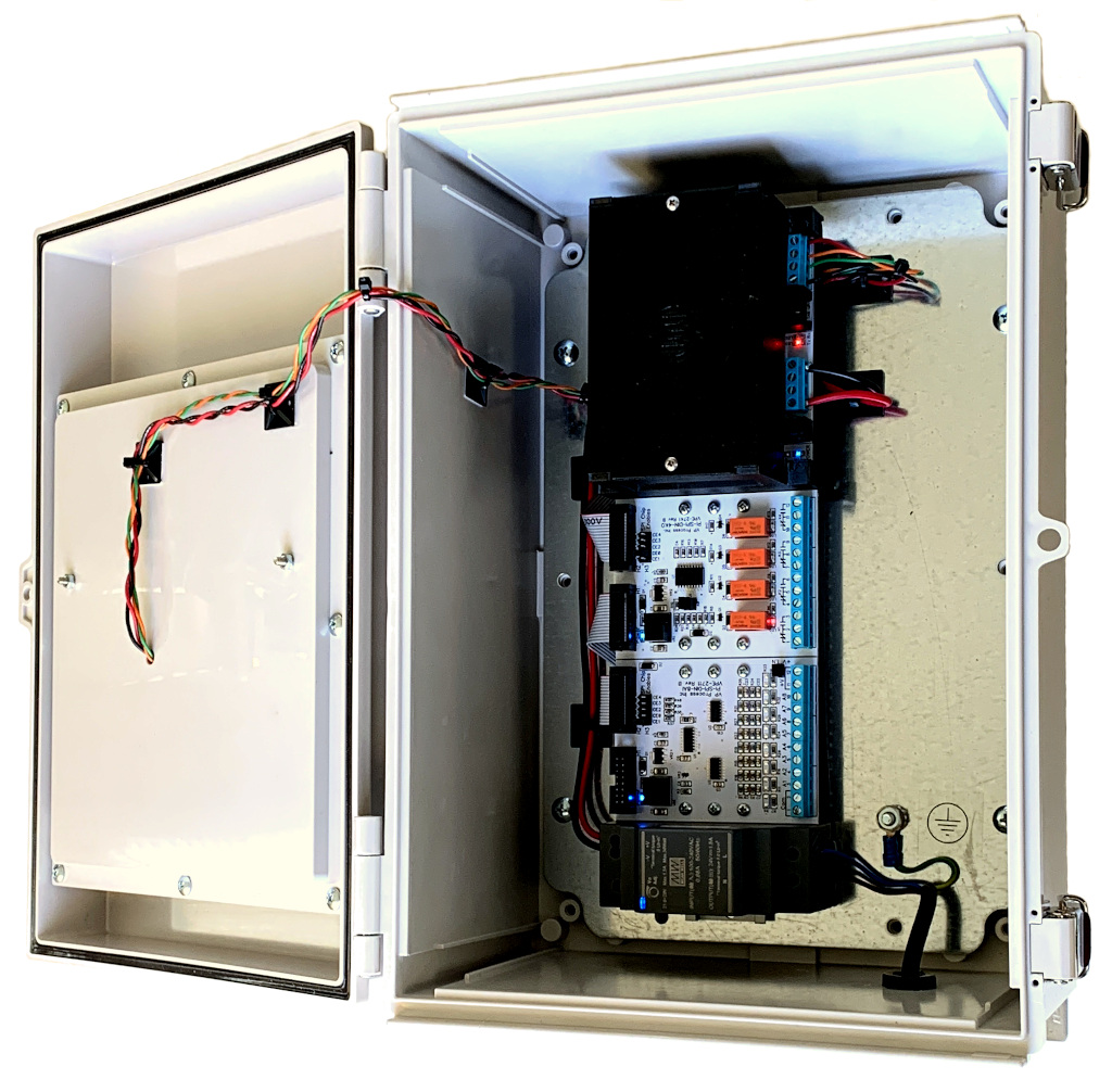
- Control Module Raspberry Pi Powered
- 4x20 Character LCD and 2 Bi-Colour Alarm Status LEDs
- IP66 Enclosure 13.78" High x 9.84" Wide x 6.3" Deep
- Separate Access Door for LCD Display Module
- 4 Function Keypad for User Interface
- 120/240 VAC Power Input
- 24 VDC 1.5 A Power Supply
Operation
Getting Started :
1. Mount the VP-KB1 controller in a suitable location for the application.
2. The power input relies on the installer to provide a suitable circuit breaker or fuse protection circuit.
3. Connect the remote sensor wiring. NOTE: 24 VDC field power is provided on the analog input module with available current of approximately 1 A. If more power for field transmitters is required, the user must install an appropriate separate power supply.
4. Connect the relay output circuits as required.
Power On :
There is a 20 Second Power On Timer to allow the processor tp boot up and stabilize. During the Power On cycle, the LCD will display the default VP-EC-RDU power on message:
Start Up Display
VP-EC-RDU
Press UP/DOWN/ENTER
Together
For Program Mode
There are 4 Main Display Screens. The different screens are accessed with the UP or DOWN Pushbuttons
Pushbutton Operation :
There are four pushbuttons, MENU, UP, ENTER and DOWN. The basic operation is UP or DOWN to select the display, ENTER to start or exit a function.
Status LEDs :
Status 1 LED Displays the alarm conditions of the sensors :
GREEN = OK
AMBER = Warning
AMBER FLASHING = Caution
RED = Critical
RED FLASHING = Sensor Fault
Status 2 LED Displays the alarm conditions of the Relays :
GREEN = OK (No relays energized)
AMBER = Alarm (One or more relays are energized)
Back to Top
Normal Operation LCD Screens :
Examples shown are for a NH3 (Ammonia) Sensor Input 1, all other sensor (2 thru 8) are disabled.
Each screen changes on either an UP or DOWN button press, the example shown is successive DOWN button presses.
Screen Number
Screen Display
Description
1. Default Display Sensor Number 1
Sensor 1
0 PPM NH3
OK
Default Display, shows the current gas value, units and alarm status for each Sensor.
If more than 1 sensor input is programmed, this display will scroll between all the active sensors.
2. Relay Programming
K1 Fault Zone 0
K2 Caution Zone 0
K3 Warning Zone 0
K4 Critical Zone 0
Shows the current Relay Programming and Zone
NOTE: Each Relay can be a different Zone
Each Sensor can be a different Zone
3. Sensor Programming 1 thru 4
P1 NH3 PPM Zn 0
P2 Disabled
P3 Disabled
P4 Disabled
Displays the Sensor Type, Units and Zone
4. Sensor Programming 5 thru 8
P5 Disabled
P6 Disabled
P7 Disabled
P8 Disabled
Displays the Sensor Type, Units and Zone
Back to Top
Programming
To enter the programming mode, press the MENU (M) pushbutton :
The "Enter Password" screen will appear
1. Enter Password
Enter Password
0000
^
The default Password for the VP-KB1 is "2018"
To enter the password :
1. Used the UP or Down pushbutton to select the first digit
2. Press the ENTER ( [] ) pushbutton to accept the value and the cursor will advance to the next digit to be entered
3. Repeat steps 1 and 2 untill all the values are entered.
NOTE: These steps are used in all the programming steps that require a value to be entered.
Once the correct password has been entered, the programming screens will appear.
2. Settings Menu
Settings
>Exit
Sensors
Relays
Use the UP or DOWN pushbuttons to select the program function.
The Exit function is always the default and will take the user back to the previous screen.
Select the "Sensors" Menu item and press "Enter"
3. Sensor Settings Menu
Sensor Settings
>Exit
Sensor 1
Sensor 2
Use the UP or DOWN pushbuttons to select the sensor to be programmed.
The display will scroll through all the sensors.
Select Sensor 1, the following screens will appear :
4. Sensor 1 Settings Menu
Sensor 1 Settings
>Exit
Enable/Disable
Type
Use the UP or DOWN pushbuttons to select the sensor parameter to be programmed.
The display will scroll through all available program variables.
Sensor Variables to be programmed:
- Enable/Disable : Select whether sensor input is active or not
- Type : Select the sensor Type - See Sensor Type Chart above
- Zone : Select the Sensor Zone - Each Sensor can have it's own zone and operate an independant Relay
- Caution Setpoint : Set the Caution (Low) Alarm Threshold
- Warning Setpoint : Set the Warning (Mid) Alarm Threshold
- Critical Setpoint : Set the Critical (High) Alarm Threshold
- Setpoing diff : Set the Differential (Deadband) Alarm Threshold
- Calibrate 4 mA : Calibrate the 4 mA Input - !! Signal Generator is required !!
- Calibrate 20 mA : Calibrate the 20 mA Input - !! Signal Generator is required !!
Select the "Relays" Menu item and press "Enter"
3. Relay Settings Menu
Relay Settings
>Exit
Relay 1
Relay 2
Use the UP or DOWN pushbuttons to select the relay to be programmed.
The display will scroll through all the relays.
Select Relay 1, the following screens will appear :
4. Relay 1 Settings Menu
Relay 1 Settings
>Exit
Type
Zone
Use the UP or DOWN pushbuttons to select the relay parameter to be programmed.
The display will scroll through all available program variables.
Relay Variables to be programmed:
- Type : Each relay can be either FAULT, WARNING, CAUTION or CRITICAL
- Zone : Select the Zone, the default is 0. If all sensors are in Zone 0 as well, the relays will operate on any sensor alarm.
- On delay : Set the time in seconds before the relay will energize when in alarm condition.
- Off delay : Set the time in seconds the relay will stay energized after the alarm condition is cleared.
Back to Top