VP-TX-120-SS

Solid State Gas Sensor Transmitter

Contents

Layout
Field Wiring
Block Diagram
Specifications
Operation
Programming and Calibration
Modbus Functions and Register List

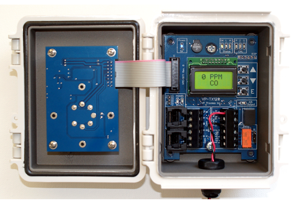
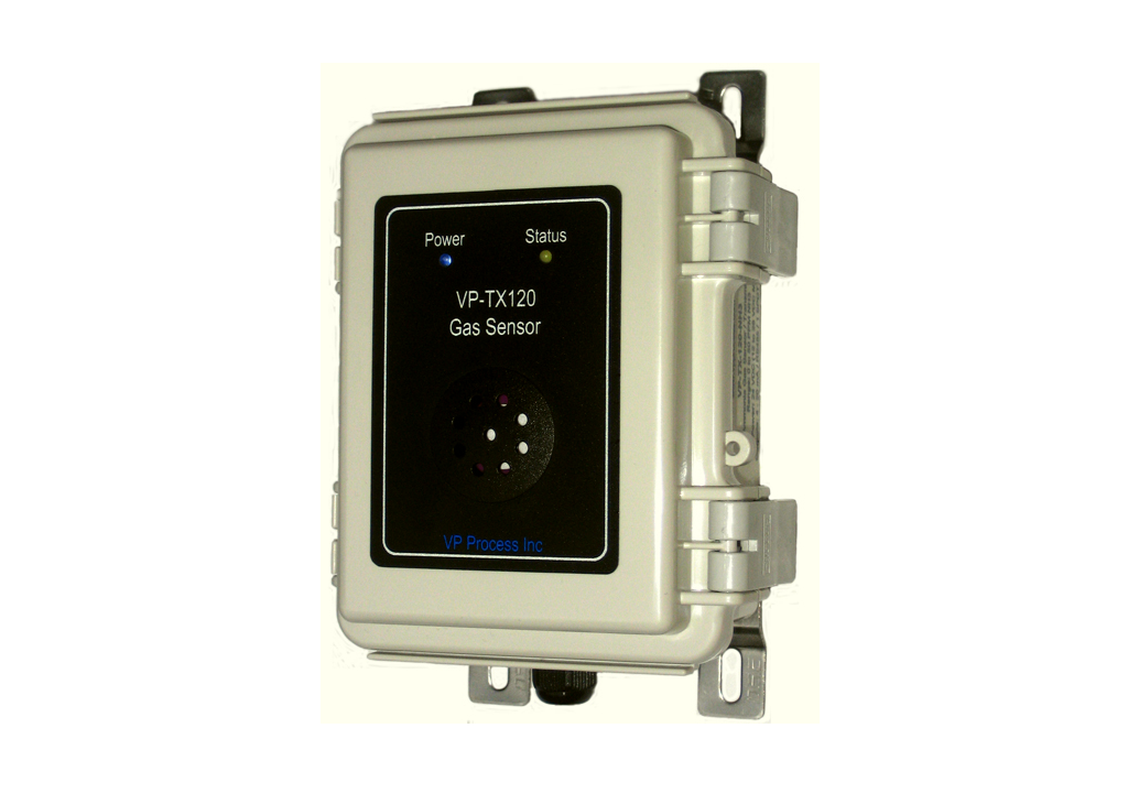
The VP-TX-120-SS is the inexpensive alternative to gas detection and environment monitoring. The combination of analog 4-20 mA output and the RS-485 digital port makes this unit the ideal choice to connect to analog controllers and digital PLC's. The choice of Solid State Gas Sensor provides accurate level readings with a life span of up to 7 years under normal applications.

Responsive image

The on board temperature sensor and %RH (Humidity) sensor can be read directly from the RS-485 port or with the LCD display which is internally mounted. The user interface consists of a Status LED, LCD and three pushbuttons. The Status LED indicates OK, LOW, MID, HIGH Alarm. The three pushbuttons and internal LCD provide a convenient calibration method. There are NO potentiometers, all programming and calibration is performed digitally from the user interface. The compact ABS enclosure is rated for IP66 of IEC 529 and NEMA 1,2,4,4x,12 and 13. The interior is EMI/RFI shielded with a nickel conductive coating. For installation convenience, the VP-TX-120-CO comes complete with mounting hardware already installed.

Standard Features

Pre-Programmed Default Sensors and Settings

Figaro Sensor Gas Type Gas Name Gas Range Units Calibration Gas Low Alarm Mid Alarm High Alarm
TGS826 NH3 Ammonia 0 - 300 PPM 300100200300
TGS832 R-134a Freon 0 - 3000 PPM 1000100020003000
TGS822 CO Carbon Monoxide 0 - 400 PPM 1003550100
TGS822 ALC Ethanol 0 - 5000 PPM 1000100020003000
TGS813 CH4 Methane 0 - 50 %LEL 20203040
TGS813 C3H8 Propane 0 - 50 %LEL 20203040
Back to Top

Transmitter Layout

Responsive image
Responsive image

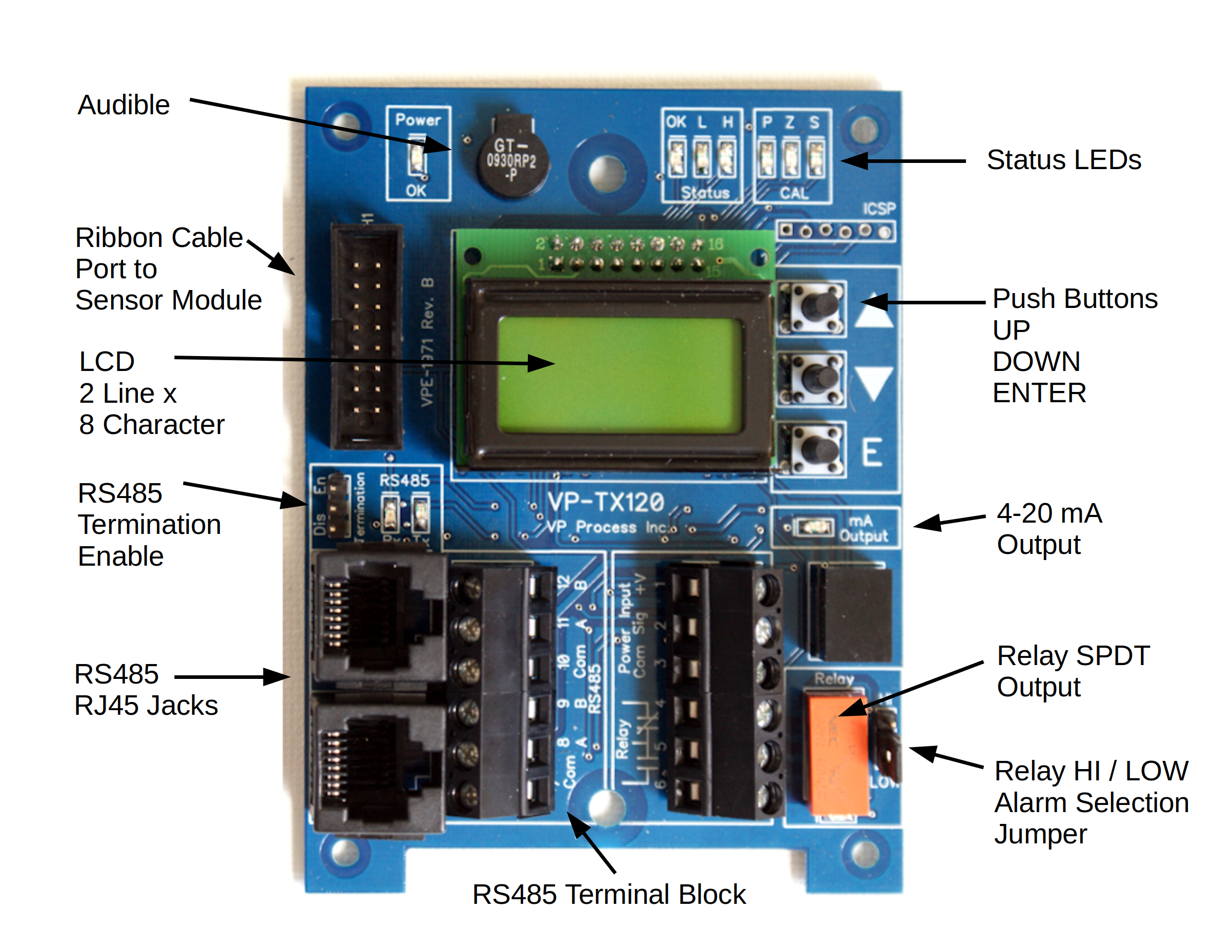
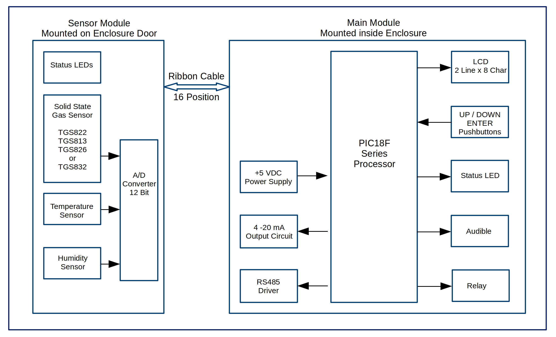
The VP-TX-120-SS has two printed circuit card assemblies:
1. The main pcb has the LCD, User Interface components, relay. RS485 Rj45 jacks, and the field wiring terminal blocks. This module is common to all the various sensor types.
2. The sensor module is mounted on the door for the enclosure and has the gas sensor, temperature sensor, humidity sensor, pwoer and status LEDs.

Back to Top

Field Wiring

Responsive image Back to Top

Block Diagram

Responsive image Back to Top

Specifications

Item Metric Value
I/O Part Name : VP-TX-120 Solid State Sensor Transmitter
Part Number : VPE-1971
Input : Figaro Series TGS Solid State Sensor
Sensor Heater Voltage : 5 VDC, +/- 0.1 VDC
Resolution : 4096 AD Counts (12 bit)
Accuracy : +/- 5% up to 100% of Full Scale for GAS Long Term Drift
Repeatability : +/- 5% of Full Scale
Linearity : +/- 10% of Full Scale
Internal Temperature Sensor : 10K Ω NTC 3380 Beta Thermistor
Internal Humidity Sensor : Honeywell HIH-5030 Series, Range 0 to 95% Non-Condensing
Sample Rate : 500 ms Default
Warm Up Time : 5 Minutes for full operation at 25 °C
24 Hours for full specification at 25 °C
Relay Output Qty : 1 SPDT
Rating 2 A
Communication Protocol : Modbus RTU RS485
Baud Rate Programmable 9600,19200 (N81)
Modbus ID Programmable 1 to 253
Termination Jumper Selectable Enable or Disable 120 Ohm
Wiring 1 RJ45 Jack, 1 sets of terminal blocks (+V, Data A, Data B, Common)
Analog Output : 4 - 20 mA
Drive (Max) 1000 Ω at 24 VDC Input Field Power
Scale Gas Range (See Above Chart)
User Interface Pushbuttons : UP. DOWN, ENTER
Status LEDs - Main Module Three Alarm Leds, OK, Low, High
Program LEDs - Main Module Three Program LEDs: PGR, SPAN, ZERO
Power ON LED - Main Module Blue, Always On
Status LED - Sensor Module OK, Low, Mid, High, Fault
Power ON LED - Sensor Module Blue, Always On
LCD 2 Line x 8 Character (Mounted on Printed Circuit Board Assembly)
Audible Key Click and High Alarm (Programmable ON or OFF)
Processor Processor : Microchip PIC18F Series
Field Connections Terminal Qty : 12
Method : Screw, Rising Cage Clamp
Torque : 0.753 N-m (4.3 Lb-in)
Screw : M3
Voltage Rating : 300 VAC
Current Rating : 15 A
Withstanding Voltage : 1.6 KV
Cross section solid conductor AWG min : 28
Cross section solid conductor AWG max : 12
Cross section stranded conductor AWG min : 28
Cross section stranded conductor AWG max : 12
Stripping Length : 6-7 mm
Physical Height: 5.11"
Width : 3.93"
Depth : 2.75"
Weight : 200 g
Material : ABS, c/w Stainless Steel Wall Mounting Brackets
Weight, Shipping (Qty. 1) : 300 g
Electrical Power Input Voltage Range (Typical : 24 VDC
Power Input (Minimum) : 9 VDC
Power Input (Maximum) : 28 VDC
Current max : 100 mA
Current typical : 75 mA
Ambient Operating Temperature : -20 to +65 °C
Storage Temperature : -40 to +85 °C
Operating Relative Humidity (non-condensing) : 0 to +95 %RH
Storage Relative Humidity (non-condensing) : 0 to +95 %RH
Protection : IP20
Warranty (Exluding Sensors) Limited Liability : Product Replacement 1 Year
Download : Warranty Statement

Back to Top

Operation

Getting Started
Connect the VP-TX-120-SS Sensor Transmitter as follows:

4 - 20 mA Output
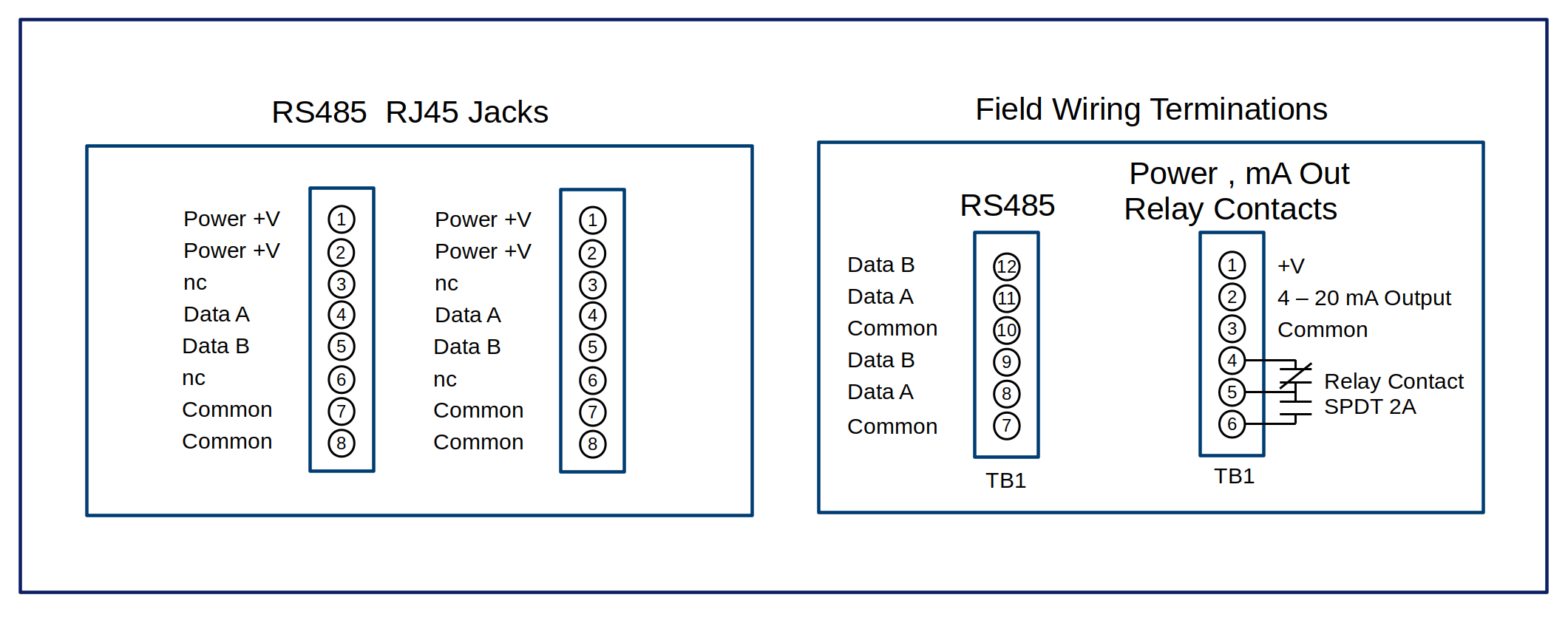
+V (24 VDC) to TB1, mA Signal Output to TB 2, Common to TB 3.

RS485 (Modbus RTU Protocol)
Data A to TB 8,11 Data B to TB 9 12, Common to TB 7, 10

NOTE: The Analog Output and RS485 are independent of each other and can be used at the same time.
For RS485 operation, the RJ45 Jack can also be used, the pinout is shown in the block diagram above.

Relay Output
NO TB 5 and 6, NC TB 5 and 4

Power On : There is a 120 Second Power On Timer to allow the sensor to stabilize. If the sensor is cold, the sensor should be allowed to stabilize for a minimum of 24 hours before performing any calibration. During the 120 Second Power On cycle, the LCD will display:

Start Up Display
  Warm Up  
  In xx  
where xx is the number in seconds to full operation

There are 6 Main Display Screens. The different screens are accessed with the UP or DOWN Pushbuttons

Pushbutton Operation : There are three pushbuttons, UP, ENTER and DOWN. The basic operation is UP or DOWN to select the display, ENTER to start or exit a function.

Back to Top

Normal Operation LCD Screens Examples shown are for a NH3 (Ammonia) Sensor

Screen Number
Screen Display
Description

1. Default Display (after the power on warm up has expired)
  0 PPM  
  NH3  
Default Display, shows the current gas value and units

2. Fault Display
  SENSOR  
  FAULT  
If the sensor is disconnected or in fault condition

3. Local Temperature Display
  T Local  
  24.2 C  
The temperature sensor is located on the bottom of the PCB ( Near TB 12)

4. Humidity Display
  RH  
  40%RH  
Note: If there is no %RH sensor connected, this display is not shown

5. Software Version Display
  TX120-SS  
  Ver 1.0  
Product Model and Software Version

6. Calibration and Programming Menus
  Setup  
  Enter  
Programming Entry point, Press ENTER to start

Note: During normal operation or programming operation, if a push button is not activated within 120 seconds, the lcd returns to the default display as shown above in point 1.

Back to Top

Programming and Calibration

Password Entry

Select the Program Entry Screen
  Setup  
  Enter  
Press Enter

Select the Password Enter Display
  Password  
  Enter  
Press Enter to access the calibration menus

OR Select the Password Exit Display to return to the main displays
  Password  
  Exit  
Press Enter to Exit and return to the main displays

Enter the Password
0000
^   
The Default Password is 1020 and is hard coded into the device. The password is used to prevent a casual user from accessing the calibration and programming menus

NOTE: To enter a value, each digit is individually programmed by using the UP or DOWN buttons to select a value. Once the desired digit is programmed, press the ENTER Key to select the next digit. After the final digit is programmed, press the ENTER key to accept the programming. (This method is typical for most programming functions.)

1000
^   
0000
 ^  
0020
  ^ 
0000
   ^

Setup, Calibration and Programming Menus
  Setup  
  Menus  
Press the UP button for the first Menu Or DOWN button to go in reverse order

Zero Calibration

Zero Calibration
  xx  
  Zero Cal  
where xx is a number representing the value of drift from zero This value can be a negative (-) or positive number, the calibration is done to get this number to a 0 value +/- 1

NOTE: Before entering the zero calibration, flow 0 gas or fresh air on the sensor to ensure a proper zero gas calibration as soon as the enter button is pressed, the zero cal value will be set


Example
  -17  
  Zero Cal  
where -17 indicates the sensor has drifted below the Zero calibration Point

Press Enter
  0  
  U EN D  
where U = UP, EN = ENTER, D = DOWN Push Buttons

The value should change to 0, if it still drifts, the UP or DOWN push buttons can be used to tweak the value to 0. Press the ENTER button to exit. Each re-entry into the Zero calibration Display Menu resets the Zero Calibration Point.

Zero Calibration is Complete

Back to Top

Span Calibration

Calibration Gas Value
  xxx  
  Cal Gas  
where xxx is a number representing value of the calibration gas to be used

The calibration gas value is used to calibrate the sensor. If the user has access to a different calibration gas concentration than the one shown on the display, press ENTER to set the new Calibration Gas Value.


Example
0300
   ^
Setting the Calibration Gas Value to 300

Span Calibration
  xx  
  Span Cal  
where xx is a number representing the current gas reading

NOTE: The user should apply the calibration gas to the sensor for an appropriate time (minimum 2 minutes) to allow the sensor to stabilize to the calibration gas value before entering the span calibration

Press Enter
  0  
  U EN D  
where U = UP, EN = ENTER, D = DOWN Push Buttons

Use the UP and DOWN push buttons to make the reading equal to the Span Calibration Gas applied. Please allow four reading updates (4 seconds) in between each button press. There is a software algorithm used where the further away the current reading is from the Cal Gas Value, the higher the adjustment value. The closer the reading is to the Cal Gas Value, the smaller the adjustment. This makes the calibration procedure very efficient.

If there is not enough signal present and a calibration is attempted, the display will show:

  ! Cal !  
  ERROR  

Back to Top

Sensor Type

Selecting a New Sensor, Type, Ranges and Setpoints
  xxx  
  Gas Type  
where XXX is current Gas Sensor Type

Enter to select a new Sensor Type, Default Range, Default Calibration Gas Value and Setpoints. Please see the Sensor Chart above for full details.

Sensor Range

Selecting a New Sensor Range
  xxx  
  Range  
where XXX is current Gas Sensor Range
Press ENTER to program a new Gas Sensor Range
NOTE: The Analog 4 - 20 mA Output tracks this value

Status LED Set Points

Status LED Low Set Point
  xxx  
  SP Low  
where XXX is current Set Point
Press ENTER to program a new Set Point

Status LED Mid Set Point
  xxx  
  SP Mid  
where XXX is current Set Point
Press ENTER to program a new Set Point

Status LED High Set Point
  xxx  
  SP High  
where XXX is current Set Point
Press ENTER to program a new Set Point

Status LED Set Point Differential
  xxx  
  SP Diff  
where XXX is current Set Point
Press ENTER to program a new Set Point

Relay ON / OFF Delays

Set the Relay ON delay in Seconds
  xx  
  On Delay  
where XX is current On Delay in Seconds
Press ENTER to program a new Setting

Set the Relay OFF delay in Seconds
  xx  
  Off Delay  
where XX is current Off Delay in Seconds
Press ENTER to program a new Setting

Audible

Enable Audible ON or OFF
  Audible  
  xx  
where XX is current setting On or Off
Press ENTER to program a new Setting

Modbus ID

Program a new MODBUS ID Number
  Modbus  
  ID = 10  
The Default Setting is ID = 10
Press ENTER to program a new ID ( 1 thru 253 )

RS485 Baud Rate

Program a new Baud Rate Number
  xx  
  Baud  
where XX is current Baud Rate Setting
Press ENTER to program a new Setting ( 9600 OR 19200 Baud)

Back to Top

Calibrate 4 mA Output

4 mA Calibration
  4 mA  
  Cal  
Press ENTER to Calibrate the 4 mA Setting

Update 4 mA Calibration
  Cal 4 mA  
  U EN D  
Measure the mA Output
Press the UP or DOWN push buttons to give a 4.00 mA Output
Press ENTER to Exit

Calibrate 20 mA Output

20 mA Calibration
  20 mA  
  Cal  
Press ENTER to Calibrate the 20 mA Setting

Update 4 mA Calibration
  Cal 20 mA  
  U EN D  
Measure the mA Output
Press the UP or DOWN push buttons to give a 20.00 mA Output
Press ENTER to Exit

Manual 4 - 20 mA Output

Test Calibration
  Manual  
  Output  
Press ENTER to set a 0 to 20 mA Output

Used for testing purposes. The analog output can be set to a pre-determined value for system testing. Once the Menu is exited, the analog output reverts back to normal operation and tracks the gas value.

Exit Programming and Calibration Menus

Exit
  Setup  
  Exit  
Press ENTER to Exit

Temperature Sensor Calibration
There is no calibration needed for the Temperature Sensor. The VP-TX120-SS has been programmed with a Steinhart equation for calculating the temperature value based on the Thermistor reading and Thermistor Beta value (B 0/50 = 3380). A 1% Thermistor is used and typically the accuracy is +/- 1 °C over the operating range of -20 to + 60 °C.

Humidity Sensor Calibration
There is no calibration required for the humidity sensor. The VP-TX120-SS has been programmed with the transfer function supplied with the Honeywell HIH series sensor. After Temperature compensation, the Humidity sensor is guaranteed to have an accuracy of +/- 3% RH from 5 to 95 % RH range, non-condensing.

Status LED
The Status LED shows the following:
GREEN = OK, RED (Flashing) = Sensor Fault, AMBER = Low Alarm, AMBER (Flashing) = Mid Alarm, RED = High Alarm

Audible
The Audible can be programmed either ON or OFF and is fixed to the HIGH alarm setting. If the Audible is enabled and ON, it can be silenced by pressing any pushbutton. The Audible is also used as a pushbutton "Click". This feature is always enabled.

Back to Top
Modbus Functions and Register List

Function Description
Function 03 Read/Write Holding Registers
Function 04 Read Input Registers
Function 06 Write Single Registers
Function 16 Write Multiple Registers

Function 03 Holding Registers

Address (Dec) Address (Hex)FunctionRead/WriteDescription
0000 0x00 Gas Reading Read Only Real Time Gas Reading x Scaler
0001 0x01 Local Temperature Reading Read Only Real Time Temperature Reading in °C x 100
0002 0x02 Local RH Reading Read Only Real Time Humidity Reading in %RH x 10
0003 0x03 Gas Scaler Read Only 10 (Fixed) (500 Reading = 50 x 10)
0004 0x04 Sensors Present Read Only 0x0001 Gas Sensor Present
0x0002 Local Temperature Sensor Present
0x0040 Humidity Sensor Present
A Value of 0x0003 = Gas and Temperature Sensors Present
0005 0x05 Product Version Read Only Firmware and Product ID
0006 0x06 - - Not Used
0007 0x07 - - Not Used
0008 0x08 - - Not Used
0009 0x09 - - Not Used
0010 0x0A - - Not Used
0011 0x0B - - Not Used
0012 0x0C - - Not Used
0013 0x0D Gas AD Counts Read Only Real Time A/D Counts (0 to 4096)
0014 0x0E Local Temperature AD Counts Read Only Real Time A/D Counts (0 to 4096)
0015 0x0F Local RH Reading AD Counts Read Only Real Time A/D Counts (0 to 4096)
0016 0x10 Push Button Satus Read Only 0x0000 = All OFF, 0x0001 = UP,
0x0002 = DOWN, 0x0004 = ENTER
or combinations of above for 2 or 3 buttons combined
0017 0x11 - - Not Used
0018 0x12 - - Not Used
0019 0x13 - - Not Used
0020 0x14 Sensor Type Read Only 0 = NH3, 1 = Freon, 2 = CO,
3 = ALC, 4 = CH4, 5 = C3H8
0021 0x15 - - Not Used
0022 0x16 Gas Sensor Zero Read / Write Zero AD Counts
0023 0x17 Gas Sensor Span Read / Write Span AD Counts
0024 0x18 Gas Sensor Cal Gas Value Read / Write Calibration Gas Value
0025 0x19 Gas Sensor Span Value Read / Write Span Value
0026 0x1A Reading Decimal Value Read / Write Decimals 0 = none, 1 or 2
0027 0x1B Status LED Low Read / Write Low Set Point Value
0028 0x1C Status LED Mid Read / Write Mid Set Point Value
0029 0x1D Status LED High Read / Write High Set Point Value
0030 0x1E Status LED Differential Read / Write Differential Set Point Value
0031 0x1F - - Not Used
0032 0x20 Analog Output 4 mA Read / Write 4 mA DA Counts
0033 0x21 Analog Output 20 mA Read / Write 20 mA DA Counts
0034 0x22 - - Not Used

Function 04 Input Registers

Address (Dec) Address (Hex)FunctionRead/WriteDescription
0000 0x00 Gas Reading Read Only Real Time Gas Reading x Scaler
0001 0x01 Local Temperature Reading Read Only Real Time Temperature Reading in °C x 100
0002 0x02 Local RH Reading Read Only Real Time Humidity Reading in %RH x 10
0003 0x03 Gas Scaler Read Only 10 (Fixed) (500 Reading = 50 x 10)
0004 0x04 Sensors Present Read Only 0x0001 Gas Sensor Present
0x0002 Local Temperature Sensor Present
0x0040 Remote Temperature Sensor Present
A Value of 0x0003 = Gas and Temperature Sensors Present
0005 0x05 Product Version Read Only Firmware and Product ID
0006 0x06 - - Not Used
0007 0x07 - - Not Used
Back to Top