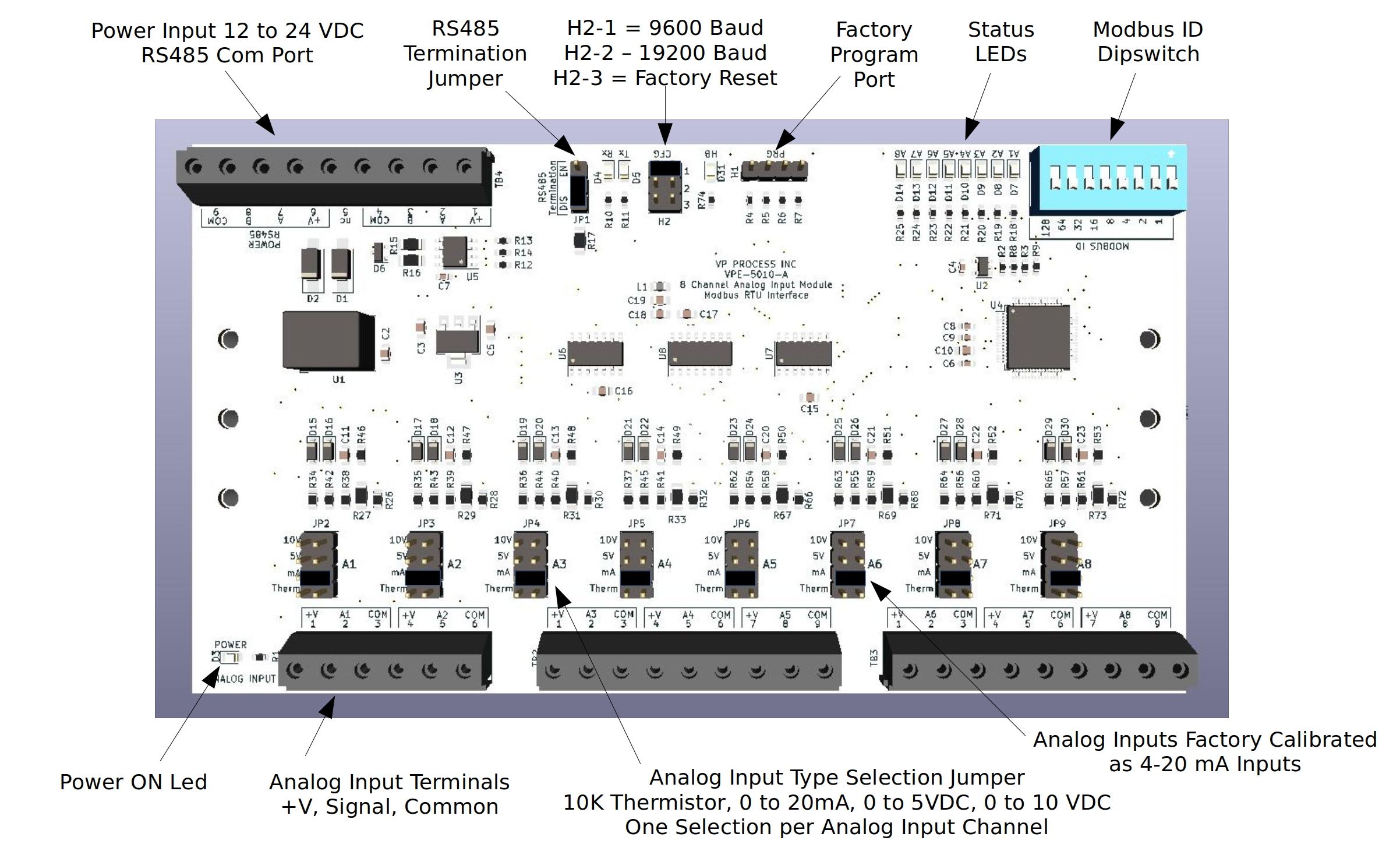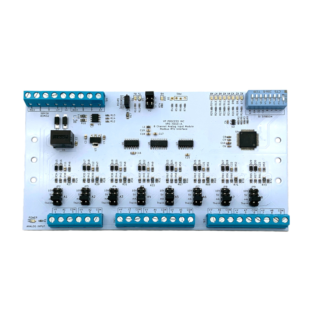
PCB
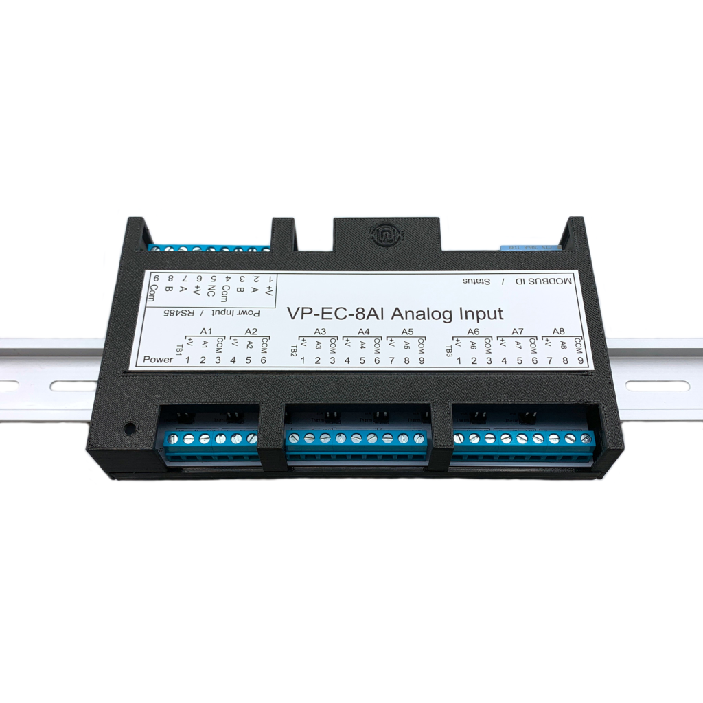
DIN Enclosure
DIN Rail Enclosures are available in Black, Blue and White
Field Wiring
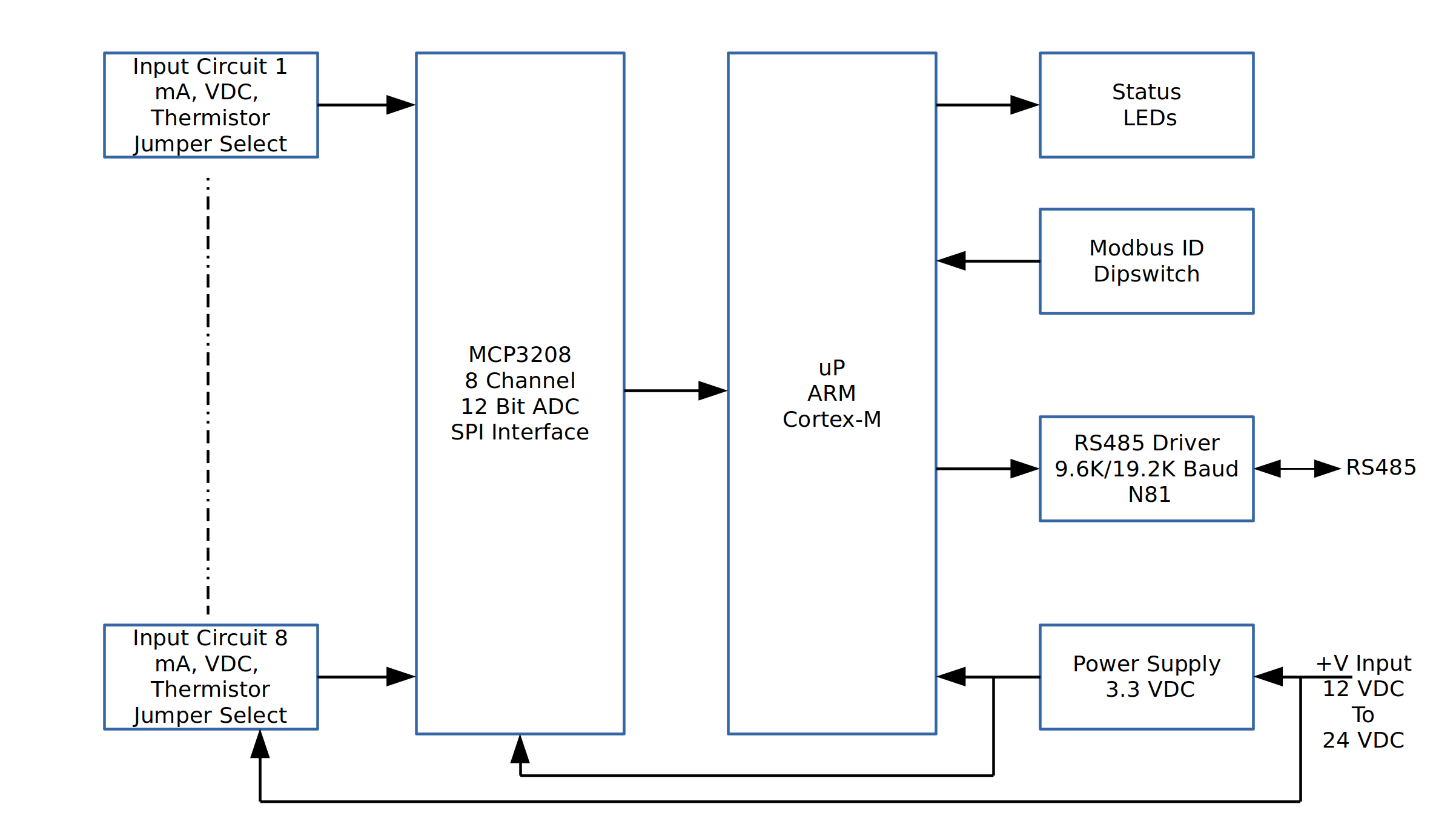
Block Diagram
Specifications
Modbus Functions and Register List
Calibration
The VP-EC-8AI is an 8 channel analog input module with a Modbus RTU RS485 interface. Each analog input can be jumper configured for:
DIN Rail Enclosures are available in Black, Blue and White
| Item | Metric | Value |
|---|---|---|
| I/O | Part Name : | Channel Analog Input Modbus RTU RS485 Interface |
| Part Number : | VPE-5010 | |
| Channels : | 8 (Single ended, reference to Common) | |
| Input Range (per channel) : | 0 to 20 mA, 0 to 5 VDC, 0 to 10 VDC, Thermistor 10K | |
| Over-range limits : | 24 mA, 12 VDC | |
| Max. Survivable Input : | 24 mA, 12 VDC | |
| Resolution : | 4096 AD Counts (12 bit) | |
| Accuracy : | +/- 0.1% mA, +/- 0.1% VDC | |
| Input Voltage Drop nominal : | 5 VDC at 20 mA per channel | |
| Sample Rate : | 512 ms Default | |
| Communication | Protocol : | Modbus RTU RS485 |
| Baud Rate | Jumper Selectable 9600,19200 (N81) | |
| Modbus ID | 8 Position Dipswitch | |
| Termination | Jumper Selectable Enable or Disable 120 Ohm | |
| Wiring | 2 sets of terminal blocks (+V, Data A, Data B, Common) | |
| Processor | Processor : | STM32 Series |
| Field Connections | Terminal Qty : | 33 |
| Method : | Screw, Rising Cage Clamp | |
| Torque : | 0.753 N-m (4.3 Lb-in) | |
| Screw : | M3 | |
| Voltage Rating : | 300 VAC | |
| Current Rating : | 15 A | |
| Withstanding Voltage : | 1.6 KV | |
| Cross section solid conductor AWG min : | 28 | |
| Cross section solid conductor AWG max : | 12 | |
| Cross section stranded conductor AWG min : | 28 | |
| Cross section stranded conductor AWG max : | 12 | |
| Stripping Length : | 6-7 mm | |
| Physical | Length (DIN Enclosure) : | 6.25" |
| Width (DIN Enclosure) : | 3.6" | |
| Height (DIN Enclosure) : | 2.3" | |
| Weight (DIN Enclosure) : | 100 g | |
| Weight, Shipping (Qty. 1) : | 200 g | |
| Electrical | Power Input Voltage Range (Typical : | 24 VDC |
| Power Input (Minimum) : | 9 VDC | |
| Power Input (Maximum) : | 28 VDC | |
| Current max : | 100 mA (Does Not include Field Transmitters) | |
| Current typical : | 75 mA (Does Not include Field Transmitters) | |
| Isolation : | None | |
| Ambient | Operating Temperature : | -20 to +65 °C |
| Storage Temperature : | -40 to +85 °C | |
| Operating Relative Humidity (non-condensing) : | 0 to +95 %RH | |
| Storage Relative Humidity (non-condensing) : | 0 to +95 %RH | |
| Protection : | IP20 | |
| Warranty | Limited Liability : | Product Replacement 1 Year |
| Download : | Warranty Statement |
| Function | Description |
|---|---|
| Function 03 | Read Holding Registers |
| Function 06 | Write Single Holding Register |
| Function 16 | Write Multiple Holding Registers |
| Address (Dec) | Description |
|---|---|
| 0000 | Input Channel 1 Fault AD Counts |
| 0001 | Input Channel 2 Fault AD Counts |
| 0002 | Input Channel 3 Fault AD Counts |
| 0003 | Input Channel 4 Fault AD Counts |
| 0004 | Input Channel 5 Fault AD Counts |
| 0005 | Input Channel 6 Fault AD Counts |
| 0006 | Input Channel 7 Fault AD Counts |
| 0007 | Input Channel 8 Fault AD Counts |
| 0008 | Input Channel 1 Zero (4mA) AD Counts |
| 0009 | Input Channel 2 Zero (4mA) AD Counts |
| 0010 | Input Channel 3 Zero (4mA) AD Counts |
| 0011 | Input Channel 4 Zero (4mA) AD Counts |
| 0012 | Input Channel 5 Zero (4mA) AD Counts |
| 0013 | Input Channel 6 Zero (4mA) AD Counts |
| 0014 | Input Channel 7 Zero (4mA) AD Counts |
| 0015 | Input Channel 8 Zero (4mA) AD Counts |
| 0016 | Input Channel 1 Span (20mA) AD Counts |
| 0017 | Input Channel 2 Span (20mA) AD Counts |
| 0018 | Input Channel 3 Span (20mA) AD Counts |
| 0019 | Input Channel 4 Span (20mA) AD Counts |
| 0020 | Input Channel 5 Span (20mA) AD Counts |
| 0021 | Input Channel 6 Span (20mA) AD Counts |
| 0022 | Input Channel 7 Span (20mA) AD Counts |
| 0023 | Input Channel 8 Span (20mA) AD Counts |
| Function | Description |
|---|---|
| Function 04 | Read Input Registers |
| Address (Dec) | Description |
|---|---|
| 0000 | Input Channel 1 AD Counts |
| 0001 | Input Channel 2 AD Counts |
| 0002 | Input Channel 3 AD Counts |
| 0003 | Input Channel 4 AD Counts |
| 0004 | Input Channel 5 AD Counts |
| 0005 | Input Channel 6 AD Counts |
| 0006 | Input Channel 7 AD Counts |
| 0007 | Input Channel 8 AD Counts |
| 0008 | Input Channel 1 Percentage 4 to 20 mA as 0 to 100%, Scaled 0 to 1000 |
| 0009 | Input Channel 2 Percentage 4 to 20 mA as 0 to 100%, Scaled 0 to 1000 |
| 0010 | Input Channel 3 Percentage 4 to 20 mA as 0 to 100%, Scaled 0 to 1000 |
| 0011 | Input Channel 4 Percentage 4 to 20 mA as 0 to 100%, Scaled 0 to 1000 |
| 0012 | Input Channel 5 Percentage 4 to 20 mA as 0 to 100%, Scaled 0 to 1000 |
| 0013 | Input Channel 6 Percentage 4 to 20 mA as 0 to 100%, Scaled 0 to 1000 |
| 0014 | Input Channel 7 Percentage 4 to 20 mA as 0 to 100%, Scaled 0 to 1000 |
| 0015 | Input Channel 8 Percentage 4 to 20 mA as 0 to 100%, Scaled 0 to 1000 |
| 0016 | Input Channel 1 Reading 4 to 20 mA Scaled 400 to 2000 |
| 0017 | Input Channel 2 Reading 4 to 20 mA Scaled 400 to 2000 |
| 0018 | Input Channel 3 Reading 4 to 20 mA Scaled 400 to 2000 |
| 0019 | Input Channel 4 Reading 4 to 20 mA Scaled 400 to 2000 |
| 0020 | Input Channel 5 Reading 4 to 20 mA Scaled 400 to 2000 |
| 0021 | Input Channel 6 Reading 4 to 20 mA Scaled 400 to 2000 |
| 0022 | Input Channel 7 Reading 4 to 20 mA Scaled 400 to 2000 |
| 0023 | Input Channel 8 Reading 4 to 20 mA Scaled 400 to 2000 |
The Module comes factory calibrated for 4 – 20 mA Input.
If other input types are used, it is up to the end user to determine their calibration values.