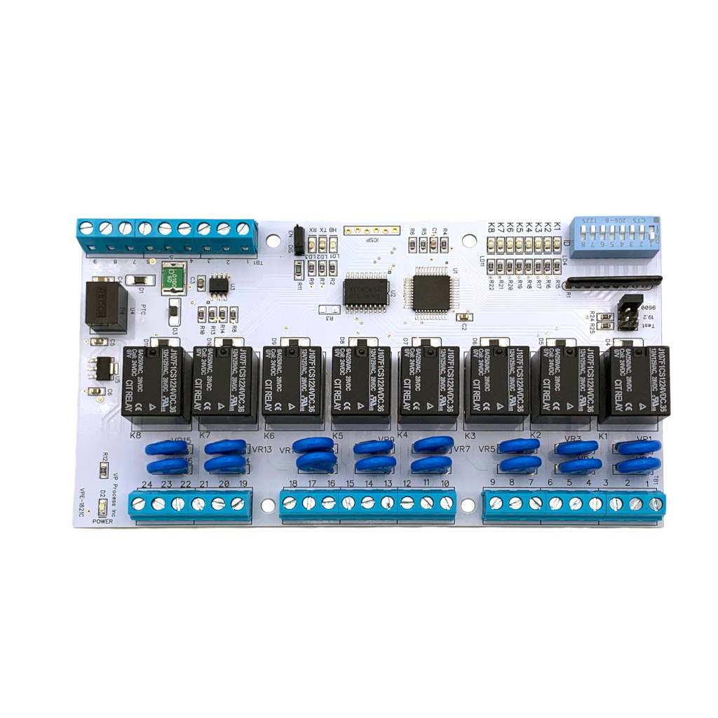
PCB
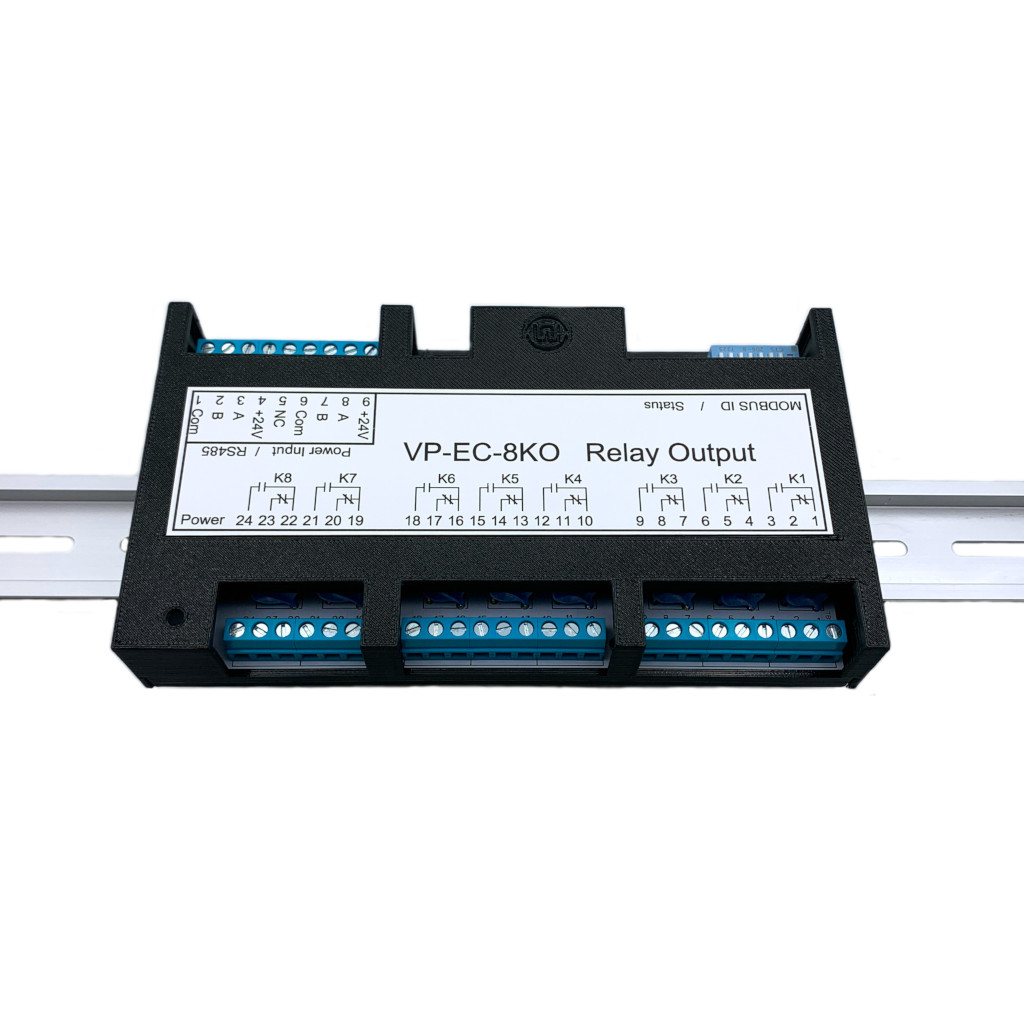
DIN Rail Enclosure
Din Rail Enclsoures are available in Black, Blue and White
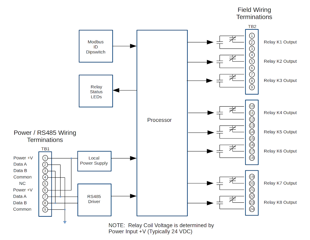
Field Wiring and Block Diagram
Specifications
Modbus Functions and Register List
Calibration
The VP-EC-8KO is an 8 channel relay output module with a Modbus RTU RS485 interface.
Din Rail Enclsoures are available in Black, Blue and White
| Item | Metric | Value |
|---|---|---|
| I/O | Part Name : | 8 Channel Relay Output Modbus RTU RS485 Interface |
| Part Number : | VPE-1821 | |
| Channels : | 8 | |
| Relay Type : | Omron G5LE-14 Series | |
| Rating : | 10A, SPDT | |
| Protection : | MOV on all contacts | |
| Communication | Protocol : | Modbus RTU RS485 |
| Baud Rate | Jumper Selectable 9.6K, 19.2K (N81) | |
| Modbus ID | 8 Position Dipswitch | |
| Termination | Jumper Selectable Enable or Disable 120 Ohm | |
| Wiring | 2 sets of terminal blocks (+V, Data A, Data B, Common) | |
| Processor | Processor : | PI18F Series |
| Field Connections | Terminal Qty : | 33 |
| Method : | Screw, Rising Cage Clamp | |
| Torque : | 0.753 N-m (4.3 Lb-in) | |
| Screw : | M3 | |
| Voltage Rating : | 300 VAC | |
| Current Rating : | 15 A | |
| Withstanding Voltage : | 1.6 KV | |
| Cross section solid conductor AWG min : | 28 | |
| Cross section solid conductor AWG max : | 12 | |
| Cross section stranded conductor AWG min : | 28 | |
| Cross section stranded conductor AWG max : | 12 | |
| Stripping Length : | 6-7 mm | |
| Physical | Length (DIN Enclosure) : | 6.25" |
| Width (DIN Enclosure) : | 3.6" | |
| Height (DIN Enclosure) : | 2.3" | |
| Weight (DIN Enclosure) : | 150 g | |
| Weight, Shipping (Qty. 1) : | 200 g | |
| Electrical | Power Input Voltage Range (Typical : | 24 VDC |
| Power Input (Minimum) : | 20 VDC | |
| Power Input (Maximum) : | 28 VDC | |
| Current max : | 200 mA (All Relays Energized) | |
| Current typical : | 75 mA (All Relays De-energized) | |
| Ambient | Operating Temperature : | -20 to +65 °C |
| Storage Temperature : | -40 to +85 °C | |
| Operating Relative Humidity (non-condensing) : | 0 to +95 %RH | |
| Storage Relative Humidity (non-condensing) : | 0 to +95 %RH | |
| Protection - DIN Option : | IP20 | |
| Warranty | Limited Liability : | 1 Year |
| Download : | Warranty Statement |
Supported Modbus Functions
| Function | Description |
|---|---|
| Function 01 | Read Coils |
| Function 05 | Write Single Coil |
| Function 15 | Write Multiple Coils |
Example 1 : Function 01 (0x01) Read Coils
| Type | Byte | Byte Qty | Value |
|---|---|---|---|
| Request | Function Code | 1 Byte | 0x01 |
| Starting Address | 2 Bytes | 0x0000 to 0xFFFF | |
| Quantity of Coils | 2 Bytes | 1 to 2000 (0x7D0) | |
| CRC Checksum | 2 Bytes | 0x**** | |
| Response | Function Code | 1 Byte | 0x01 |
| Byte Count | 1 Bytes | N* (N= Quantity of Outputs / 8, if the remainder is different of 0 ⇒N = N+1) | |
| Coil Status | n Bytes | n = N or N+1 | |
| CRC Checksum | 2 Bytes | 0x**** | |
| Error | Function Code | 1 Byte | 0x81 |
| Exception Code | 1 Bytes | 01 or 02 or 03 or 04 | |
| CRC Checksum | 2 Bytes | 0x**** |
Example 2 : Function 05 (0x05) Write Single Coil
| Type | Byte | Byte Qty | Value |
|---|---|---|---|
| Request | Function Code | 1 Byte | 0x05 |
| Output Address | 2 Bytes | 0x0000 to 0xFFFF | |
| Output Value | 2 Bytes | 0x0000 or 0xFF00 | |
| CRC Checksum | 2 Bytes | 0x**** | |
| Response | Function Code | 1 Byte | 0x05 |
| Output Address | 2 Bytes | 0x0000 to 0xFFFF | |
| Output Value | 2 Bytes | 0x0000 or 0xFF00 | |
| CRC Checksum | 2 Bytes | 0x**** | |
| Error | Function Code | 1 Byte | 0x85 |
| Exception Code | 1 Bytes | 01 or 02 or 03 or 04 | |
| CRC Checksum | 2 Bytes | 0x**** |
Example 3 : Function 15 (0x0F) Write Multiple Coils
| Type | Byte | Byte Qty | Value |
|---|---|---|---|
| Request | Function Code | 1 Byte | 0x0F |
| Starting Address | 2 Bytes | 0x0000 to 0xFFFF | |
| Qty of Outputs | 2 Bytes | 0x0001 to 0x07B0 | |
| Byte Count | 1 Bytes | N* | |
| Outputs Value | N * 1 Byte | Coil Values | |
| CRC Checksum | 2 Bytes | 0x**** | |
| Response | Function Code | 1 Byte | 0x0F |
| Starting Address | 2 Bytes | 0x0000 to 0xFFFF | |
| Qty of Outputs | 2 Bytes | 0x0001 to 0x07B0 | |
| CRC Checksum | 2 Bytes | 0x**** | |
| Error | Function Code | 1 Byte | 0x8F |
| Exception Code | 1 Bytes | 01 or 02 or 03 or 04 | |
| CRC Checksum | 2 Bytes | 0x**** |
The module does not require any calibration.