VP-EC-RDU

LCD Display Modbus RTU RS485

Contents

Field Wiring
Specifications
Menu and Programming Functions
Modbus Functions and Register List

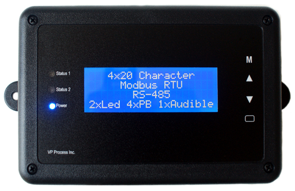
The VP-EC-RDU LCD Display is the perfect addition to any embedded controls system that uses the MODBUS protocol and has an RS485 port. The easy to read 4 line x 20 character display is simple to use. Just write ASCII characters to the applicable holding registers, along with the status LEDs and Audible, and the VP-EC-RDU does the rest.

Each Status LED can be programmed Green, Amber, Red or Off with Solid, Slow Flash or Fast Flash operation. This is perfect for alarm indication in PLC applications. The four user buttons can be read and programmed for different functions as required by the user's application. The local Temperature Sensor located on the main PCB can be read by Modbus Function 03, or can be simply displayed on the LCD.

Responsive image

Standard Features:


Field Wiring

Responsive image

Specifications

Item Metric Value
I/O Part Name : LCD Display Modbus RTU RS485
Part Number : VP-EC-RDU
Temperature Sensor : Located on the main printed circuit board
NTC 10K Ω Thermistor, 3380 Beta
Range: -20 to +70 °C (Steinhart-Hart Equation)
Resolution : 4096 AD Counts (12 bit)
Accuracy : +/- 0.5 °C
LCD Display Format : 20 Character x 4 Lines Type: STN-LCD Blue
Colour : White Characters on Blue Background
Backlight : LED
Communication Protocol : Modbus RTU RS485
Baud Rate Programmable 9600 to 115.2K (N81)
Modbus ID Programmable ID 1 to 253
Termination Jumper Selectable Enable or Disable 120 Ohm
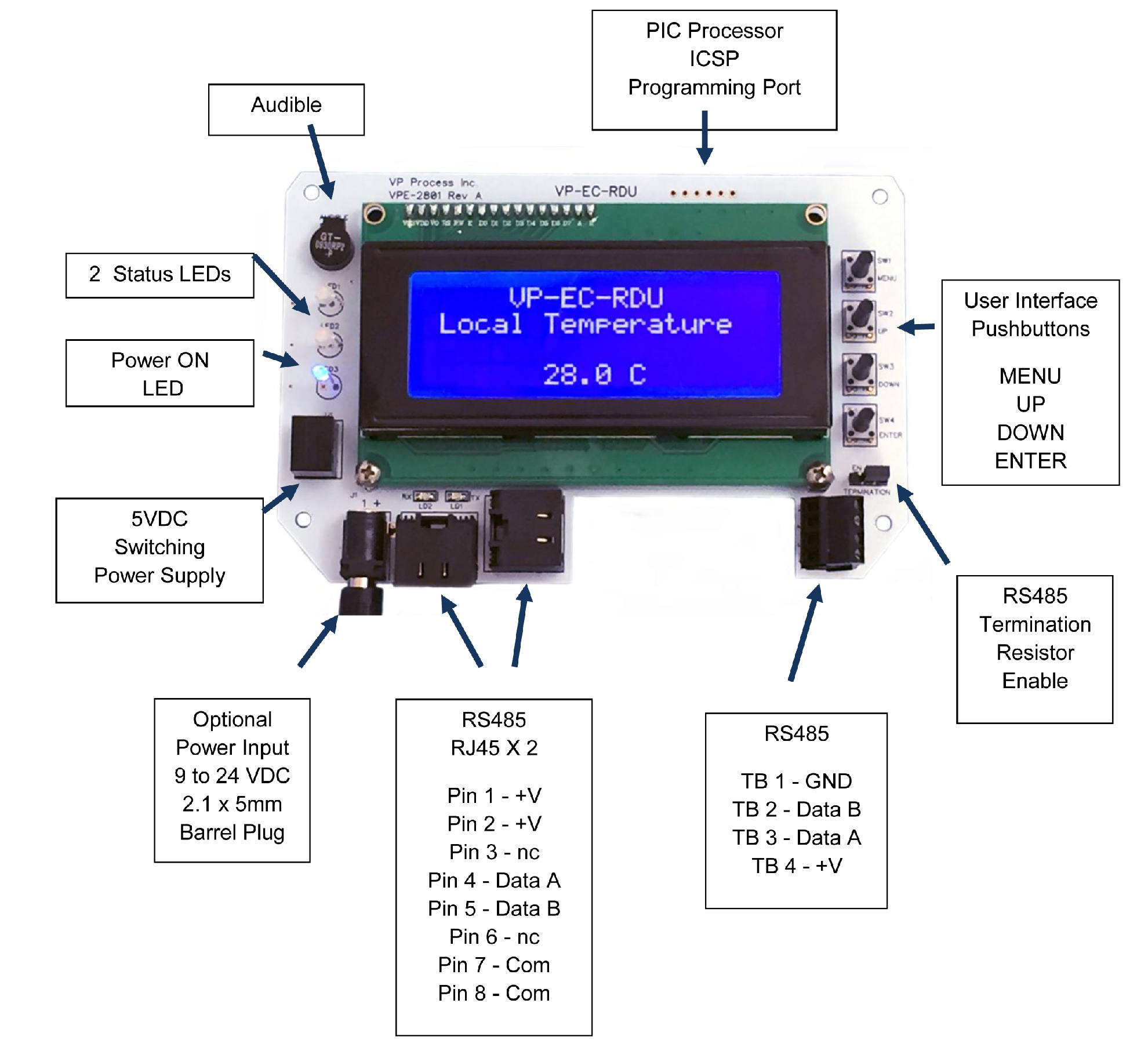
Wiring 2 RJ45 Jacks, 1 set of terminal blocks (+V, Data A, Data B, Common)
Processor Processor : PIC18F Series
Physical Length : 6.0"
Width : 4.0"
Height (Above backplane) : 1.13"
Weight : 200 g
Weight, Shipping (Qty. 1) : 300 g
Enclosure Material : Flame Retardant ABS, Flame Rating: ULV94V-0
EnclosureColour : Black
Electrical Power Input Voltage Range (Typical : 24 VDC
Power Input (Minimum) : 9 VDC
Power Input (Maximum) : 28 VDC
Power Input Jack : 2.1 x 5 mm Barrel Plug
Current max : 100 mA
Current typical : 75 mA
Isolation : None
Ambient Operating Temperature : -20 to +65 °C
Storage Temperature : -40 to +85 °C
Operating Relative Humidity (non-condensing) : 0 to +95 %RH
Storage Relative Humidity (non-condensing) : 0 to +95 %RH
Protection : IP20
Warranty Limited Liability : 1 Year From Time of Purchase
Download : Warranty Statement

Back to Top

Menu and Programming Functions

To access the MENU and programming functions, press the UP, DOWN and ENTER pushbuttons simultaneously. The basic operation is UP or DOWN to select the display, ENTER to start or exit a function. If the backlight is OFF, any button press will turn the backlight ON.
The user interface is password protected (4 digit PIN). Once entered, the user can select by using the Up, Down and Enter pushbuttons:

Standard Menu Displays:

NOTE: If the user does not press a pushbutton within the "Reset Menu Time", typically 60 seconds, the VP-EC-RDU will return to normal operation and wait for the next valid Modbus command. If no valid commands are transmitted, the VP-EC-RDU will continue to show the last screen displayed. To re-enter the local and programming menus, the user must press UP, DOWN and ENTER simultaneously again.

Temperature Sensor :

There is no calibration required for the Temperature Sensor. The VP-EC-RDU has been programmed with a Steinhart-Hart equation for calculating the temperature value based on the Thermistor reading and Thermistor Beta value (B 0/50 = 3380). A 1% Thermistor is used and typically the accuracy is +/- 1 °C over the operating range of -20 to +70 °C.
The temperature value can be read via Holding Register Address 50 (0x0032).
The reading has a x100 scaler, ie: 25.0 °C would would have a reading of 2500.

Audible :

The VP-EC-RDU has an audible buzzer. The audible can be enabled or disabled from the main menu. When enabled, it provides a "Click" whenever a key is pressed. When turned on by writing a "1" to the Audible Holding Register, the audible will chirp once per second. When enabled and turned ON, it can be silenced by pressing the ENTER pushbutton.

Program Menu Displays:

Programming a New Value: After a programming value has been seleected (Passwordm, Modbus ID, etc.), the Cursor ^ will start at the left most digit, and the UP / DOWN buttons are pressed until the desired value is reached. To accept the value, the used presses ENTER and the Cursor will advance to the next digit where the selection process is repeated until all required digits are entered.
For a value of "0000" (the default password value), the ENTER button is pressed 4 times.

Programming Status LEDs:

The VP-EC-RDU has 2 Bi-Colour Status LEDs and 1 BLue Power ON LED.
The Status LEDS have 3 modes of operation and 3 colours:

Code (Hex) Status LED Operation
0x00 OFF
0x01 GREEN SOLID
0x11 GREEN SLOW FLASH
0x21 GREEN FAST FLASH
0x02 AMBER SOLID
0x12 AMBER SLOW FLASH
0x22 AMBER FAST FLASH
0x04 RED SOLID
0x14 RED SLOW FLASH
0x24 RED FAST FLASH

Reading Pushbuttons:

The VP-EC-RDU has 4 user pushbuttons that can be read via The Status LEDS have 3 modes of operation and 3 colours:

Code (Hex) Pushbutton Operation
0x00 No buttons pressed
0x08 MENU button pressed
0x04 UP button pressed
0x02 DOWN button pressed
0x01 ENTER button pressed

Back to Top


Modbus Functions and Register List

Function Description
Function 03 Read Holding Registers
Function 16 Write Multiple Holding Register
Address (Dec) Address (Hex)Description Function
00 0x0000 LCD Line 1 ASCII Character 1 High Byte, Character 2 Low Byte Read/Write
01 0x0001 LCD Line 1 ASCII Character 3 High Byte, Character 4 Low Byte Read/Write
02 0x0002 LCD Line 1 ASCII Character 5 High Byte, Character 6 Low Byte Read/Write
03 0x0003 LCD Line 1 ASCII Character 7 High Byte, Character 8 Low Byte Read/Write
04 0x0004 LCD Line 1 ASCII Character 9 High Byte, Character 10 Low Byte Read/Write
05 0x0005 LCD Line 1 ASCII Character 11 High Byte, Character 12 Low Byte Read/Write
06 0x0006 LCD Line 1 ASCII Character 13 High Byte, Character 14 Low Byte Read/Write
07 0x0007 LCD Line 1 ASCII Character 15 High Byte, Character 16 Low Byte Read/Write
08 0x0008 LCD Line 1 ASCII Character 17 High Byte, Character 18 Low Byte Read/Write
09 0x0009 LCD Line 1 ASCII Character 19 High Byte, Character 20 Low Byte Read/Write
10 0x000A LCD Line 2 ASCII Character 1 High Byte, Character 2 Low Byte Read/Write
11 0x000B LCD Line 2 ASCII Character 3 High Byte, Character 4 Low Byte Read/Write
12 0x000C LCD Line 2 ASCII Character 5 High Byte, Character 6 Low Byte Read/Write
13 0x000D LCD Line 2 ASCII Character 7 High Byte, Character 8 Low Byte Read/Write
14 0x000E LCD Line 2 ASCII Character 9 High Byte, Character 10 Low Byte Read/Write
15 0x000F LCD Line 2 ASCII Character 11 High Byte, Character 12 Low Byte Read/Write
16 0x0010 LCD Line 2 ASCII Character 13 High Byte, Character 14 Low Byte Read/Write
17 0x0011 LCD Line 2 ASCII Character 15 High Byte, Character 16 Low Byte Read/Write
18 0x0012 LCD Line 2 ASCII Character 17 High Byte, Character 18 Low Byte Read/Write
19 0x0013 LCD Line 2 ASCII Character 19 High Byte, Character 20 Low Byte Read/Write
20 0x0014 LCD Line 3 ASCII Character 1 High Byte, Character 2 Low Byte Read/Write
21 0x0015 LCD Line 3 ASCII Character 3 High Byte, Character 4 Low Byte Read/Write
22 0x0016 LCD Line 3 ASCII Character 5 High Byte, Character 6 Low Byte Read/Write
23 0x0017 LCD Line 3 ASCII Character 7 High Byte, Character 8 Low Byte Read/Write
24 0x0018 LCD Line 3 ASCII Character 9 High Byte, Character 10 Low Byte Read/Write
25 0x0019 LCD Line 3 ASCII Character 11 High Byte, Character 12 Low Byte Read/Write
26 0x001A LCD Line 3 ASCII Character 13 High Byte, Character 14 Low Byte Read/Write
27 0x001B LCD Line 3 ASCII Character 15 High Byte, Character 16 Low Byte Read/Write
28 0x001C LCD Line 3 ASCII Character 17 High Byte, Character 18 Low Byte Read/Write
29 0x001D LCD Line 3 ASCII Character 19 High Byte, Character 20 Low Byte Read/Write
30 0x001E LCD Line 4 ASCII Character 1 High Byte, Character 2 Low Byte Read/Write
31 0x001F LCD Line 4 ASCII Character 3 High Byte, Character 4 Low Byte Read/Write
32 0x0020 LCD Line 4 ASCII Character 5 High Byte, Character 6 Low Byte Read/Write
33 0x0021 LCD Line 4 ASCII Character 7 High Byte, Character 8 Low Byte Read/Write
34 0x0022 LCD Line 4 ASCII Character 9 High Byte, Character 10 Low Byte Read/Write
35 0x0023 LCD Line 4 ASCII Character 11 High Byte, Character 12 Low Byte Read/Write
36 0x0024 LCD Line 4 ASCII Character 13 High Byte, Character 14 Low Byte Read/Write
37 0x0025 LCD Line 4 ASCII Character 15 High Byte, Character 16 Low Byte Read/Write
38 0x0026 LCD Line 4 ASCII Character 17 High Byte, Character 18 Low Byte Read/Write
39 0x0027 LCD Line 4 ASCII Character 19 High Byte, Character 20 Low Byte Read/Write
40 0x0028 STATUS LED 1 Read/Write
41 0x0029 STATUS LED 2 Read/Write
42 0x002A Audible Read/Write
43 0x002B Not Used Read
44 0x002C Not Used Read
45 0x002D Not Used Read
46 0x002E Not Used Read
47 0x002F Not Used Read
48 0x0030 Not Used Read
49 0x0031 Not Used Read
50 0x0032 Temperature Deg.C x 100 Scale ie: 25 Deg C reads 2500 Read/Write
51 0x0033 Modbus ID Read/Write
52 0x0034 Baud Rate Read/Write
53 0x0035 LCD Contrast Value Read/Write
54 0x0036 LCD Backlight Enable Read/Write
55 0x0037 Audible Enable Read/Write
56 0x0038 Menu Reset Time Read/Write
57 0x0039 Password Read/Write
58 0x003A Pushbutton Values Read
59 0x003B Not Used Read
Back to Top